42 Interior, Damong Maliit Rd, Novaliches, Quezon City, 1123 Metro Manila
-
ADDRESS
-
CONTACT
E-Mobility Department
0939-903-9083Electrical and Sales Department
0917-851-0614All Department
8398-1877Sales Inquiry: sales [at] pesin.com.ph
42 Interior, Damong Maliit Rd, Novaliches, Quezon City, 1123 Metro Manila
E-Mobility Department
0939-903-9083
Electrical and Sales Department
0917-851-0614
All Department
8398-1877
Sales Inquiry: sales [at] pesin.com.ph
Directional power protection (ANSI 32) is used where a generator runs in parallel to another generator or a utility. It has two forms, overpower and underpower.
Directional Overpower and Underpower protection calculate the total apparent power flow through the recloser based on the voltages and currents. Directional Overpower operates when the measured apparent power exceeds a threshold limit. Directional Underpower protection operates when the measured apparent power falls below the threshold limit. In both the cases the protection operates, and the generator is disconnected due to a protection trip and/or an alarm is raised.
Directional power protection is applicable to Three Phase, Two Phase, Single Phase and Single Triple reclosers.
Overview
Directional overpower and underpower can be used in several different applications. The following section will highlight some of the most common. However, let’s first consider the general operating conditions of each element.
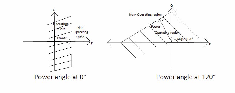
To describe the operation of the PDOP element, consider the following diagram:
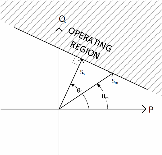
Where:
Ss = Set apparent power
θs = Set power angle
Sm = Measured apparent power
θm = Measured power angle
Operation will occur if:
Sm > Ss/[sin(θs) * sin(θm) + cos(θs) * cos(θm)]
Note: Checks are required to ensure appropriate sign of trigonometric functions.
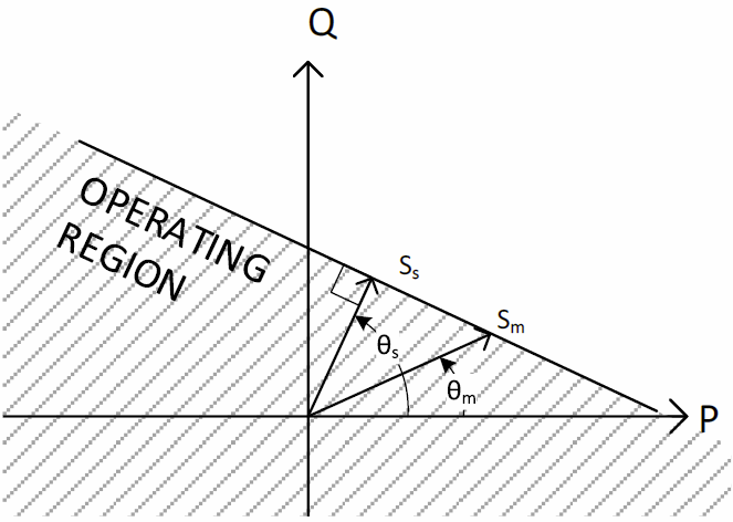
Similarly, the operation of the PDUP element can be described by the following formula:
Sm< Ss/[sin(θs) * sin(θm) + cos(θs) * cos(θm)]
Note: As per PDOP, checks are required to ensure appropriate sign of trigonometric functions.
It can be noted from the above diagrams that the further the measured angle is from the set point, the higher the measured value is out to the threshold. As this difference in angle approaches 90°, the value for Sm approaches infinity and, for any value outside of ±90°, Sm cannot pass the threshold. Thus at these angles, regardless of the power measured, for overpower it will never operate and for underpower it will always operate.
Having discussed the general characteristics of directional power protection, let us now consider some specific applications.
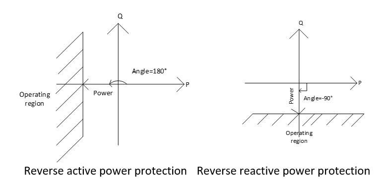
Reverse power
If a generator is connected to the grid or in parallel with another generator and the prime mover fails, energy can flow back into the alternator and attempt to drive the generator as a motor. To avoid this, directional overpower can be used to detect when the power flows in the reverse direction and disconnect the generator from the source.
For reverse active power protection, the power angle should be set to 180°, and for reverse reactive power protection, the angle should be set to -90°. This is illustrated below:
Power limitation
PDOP can also be used to limit the output of a generator. There are two situations that this may be of interest for protection. Firstly, it can be used to maintain operation within components of the generator’s capability curve. Depending on the desired characteristic, ie over/under excitation or armature current, the angle can be set to trip if the generator falls outside the limit.
The second situation where power limitation may be of value is where a network connection includes contractual requirements to limit real or reactive power to/from a utility. To achieve this, PDOP can be used to isolate the recloser or set an alarm on real or reactive power by adjusting the angle to 0° or 90° respectively.
Underpower protection
Underpower protection can be used to prevent a generator from overspeed conditions when large loads are disconnected from its network. The operating characteristics for underpower are shown below:
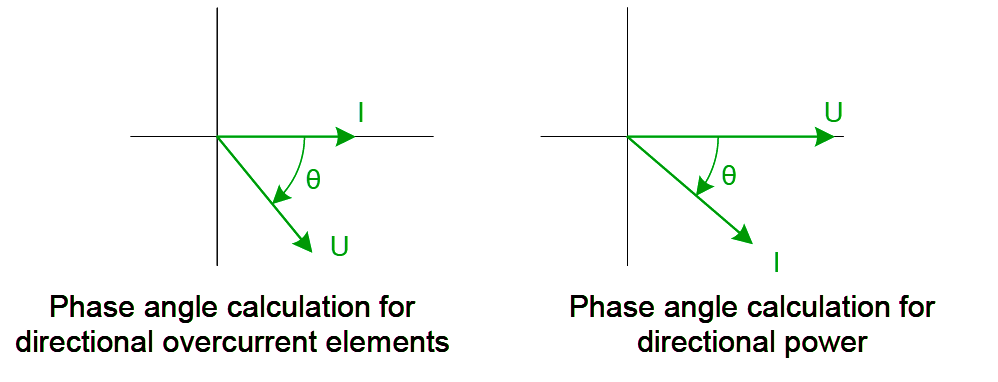
Differences Between Directional Overcurrent and Directional Power Direction Detection
NOJA Power’s set of directional protections provide both conventional overcurrent directional elements as well as directional power protection. The overcurrent directional elements and power flow elements are calculated separately and, under certain conditions, can show reversed signs on the phase angle for directional events. This is because the overcurrent elements calculate the phase angle going from the current to the voltage, while the power flow elements use the method defined by the IEEE standards, which states the phase angle as being from the voltage to current.
“Directional Power functionality extends the capability of our recloser range to be used as distributed generator circuit breakers,” reports NOJA Power Group Managing Director Neil O’Sullivan.
Conclusion
Directional Power Protection is available as part of the 1.25 Firmware for NOJA Power’s RC10 and RC15 controllers. A comprehensive application note on configuration of this functionality is available from NOJA Power. To find out more, visit www.nojapower.com.au or contact your local NOJA Power Distributor.